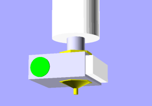
OverlapStrap Extruder Head 0.2

The first extruder head that my Dad made for me a while back had a number of pitfalls

  • It was difficult to drill a 0.5mm hole (he broke several drill bits trying to make it)
  • The resistor wasn’t a very tight fit in the aluminum block.
  • The thermistor was attached using Thermic Seal which despite being rated to 1250 °C would crumble and fall out.

So my Dad kindly offered to make a new and improved version based on some specifications and designs that we came up with together.

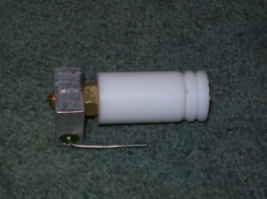
Rather than try to drill a 0.5mm hole I bought an already fabricated nozzle. Quite a few companies make these now specifically for reprap printing machines including Makerbot, ReprapStores, MakerGear and ReprapSource.

My Dad turned down the nozzle to a round insert that could be put directly into the aluminum heater block. The other addition was a PTFE thermistor clamp to hold the thermistor on using two m3 screws rather than glue.
OverlapStrap Y Chassis Rebuild

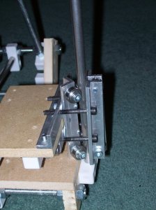
For some reason my Y Chassis started to stiffen up such that the leadscrew would pull out of the silicone tubing attaching it to the stepper. Although I managed to get it working again with the leadscrew, I figured that this would not be much good when I upgraded to belts. There were a couple of other niggles I had with the design, so I decided to redesign and rebuild the chassis. This time rather than using fixit blocks to act as clamps I decided to go back to the tried and tested aluminum angle design.

Since the build surface is raised above the chassis using PTFE stands, I didn’t need to do nearly any counter-sinking of holes, as before.

All the OverlapStrap drawings have been updated to reflect the changes.

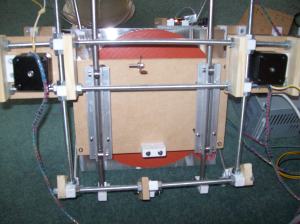
By the way, If anyone is wondering what the big red thing is on the bottom of the bed its a huge 600W, 9″ Silicone heater for my heated bed. I will blog more about it when its finished but here is a sneak peak

OverlapStrap X Carriage

Here is the latest photo of my OverlapStrap I have made quite a lot of progress on the X axis Carriage. As you can see the basic idea is the same as the Z skates and Z rollers previously posted. Also mounted is the CrudeStruder. I feel like i am very close to getting things working, all the electronics all also ready they are just waiting to be connected up. I just need to re-inforce a few things, tweak a few other things, and hope that the whole thing comes together as planned.

OverlapStrap Fixit Blocks

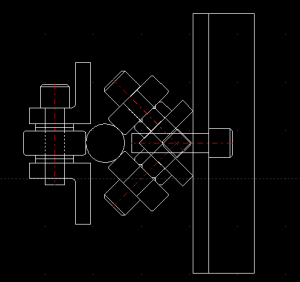
“Fixit blocks” are the bread and butter for Bodgeit’s Repstrap Bertha and my own OverlapStrap design. They are convenient little fixing blocks sold by:

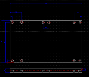
Unfortunately for people living outside the UK these blocks seem to be difficult to source. I am afraid that I also don’t have a solution for people wanting to buy these blocks from a supplier in their own country. However I am willing to re-sell packs of blocks via ebay, and ship internationally so if anyone is interested drop me an email. It seemed to me that also no one has drawn accurate drawings of these blocks for anyone who was interested in making their own. So here are the drawings below

The drawing is also available here as a DXF file.

Also for anyone trying to source these in other countries, here are some potentially useful search terms:
Modesty Block
Jointing Blocks
Knock Down Block
Knock Down Fittings
Fixit Block
Fixing Block
Cabinet Fixing Block
Viereck Möbelverbinder – German for: Quadrilateral Furniture Connector
Cupboard Connector Block

There is also something very similar, but not quite the same in the USA. I think in the USA they might be known as ‘Knock Down’ fittings/connectors.

OverlapStrap CrudeStruder

Sometimes you think you have come up with a simple design, but when you come to real-ise that design it turns out to be much harder than you imagined to make.

So I went back to the drawing board, and came up with something even simpler. This is what I have come up with, the crudestruder.

There is nothing really innovative about this design, its just a piece of MDF with mounting holes for a NEMA 17 and some 15mm copper pipe clips to hold on the thermal barrier. I used another short piece of 16mm PTFE rod with a 4.0mm hole to act as a filament guide. The pinch-wheel is just one of the standard mendel m4 bearings, and is held using a flange of aluminium that I cut off of my original stock of aluminium angle. This pinch wheel mount is held using the same m3 bolts that hold the NEMA in place. The top hole of the mount was cut into a slot to allow minor adjustment. I use a conrad electronics splined model car insert to provide grip on the drive shaft.

OverlapStrap progress and firmware modification

I have completed the Y and Z axes now of my OverlapStrap. I was originally planning to only use one Z axis motor and use one of the syncroflex belts that I bought for the Mendel to drive the two lead screws. But when I saw the price of the cheapest aluminium timing pulleys that I could find, I decided it was cheaper and simpler just to use two stepper motors for the Z axis instead

At this stage I also intend to drive the Y and X axis using lead screws. This required some modifications to the reprap firmware. Annoyingly there are preferences in the reprap software for features that don’t exist. I am a strong believer of YAGNI and also think that Green Code is a violation of this principle, so I was a bit annoyed to find both of these practices employed in the reprap code. Anyway, once I got over it and realised that the software preference for steps/mm had no effect on the hardcoded steps/mm defined in the configuration.h of the reprap firmware I was able to change it and upload the new firmware.

I have a feeling that such a low steps/mm setting will lead to printing problems when overlapstrap is complete, however I have a plan to mitigate these problems. I intend to bootstrap some basic parts using the leadscrews and then upgrade overlapstrap to a belt drive version using these parts. I will need to print a belt splitter jig, and some drive pulleys.

OverlapStrap Z Roller

I have finished building the Z axis roller that is mounted on the other Z axis rail. I really liked the axes design that Ed has used for mendel. I can imagine that if the Z Axis rails were not exactly parallel, and I had used two identical skates, then there would be the possibility that the skates would jam either at the top or bottom of the axes.
My design includes a 1/2″ x 1/8″ aluminium bar that is made by cutting an edge off a length of aluminium angle that I have used before.

OverlapStrap Y-Roller and Chassis Drawings


Here are a few extra drawings of the parts shown in the photo from the post I did a few weeks ago.
The chassis is made from 12mm thick mdf. I chose 12mm thick mdf so that it would be the same width as the original parts that I made from 12mm thick timber, as such someone wanting to make both those parts and the chassis on a cnc router machine could make it from one sheet. I am not really sure why I chose 12mm thick for corner parts, it just seemed like a good thickness at the time.
I think its important to give as much detail as possible so that anyone else wanting to make one could do so, and so that people can make improvements. Well, I suppose that’s the whole point of open source.

As usual the drawings are here