Some time ago Nophead did some experiments to investigate why holes printed by reprap machines come out undersized.
I’ve also noticed this in my prints and have in some cases manually just ‘added a bit’ and re-printed the part. This isn’t very methodical so I decided to give Nopheads polyholes compensation a try. However even on paper the hole sizes suggested seem to be lower than some of the values I found by trial and error.
I decided to do a formal test and came up with the following OpenSCAD script. I have a full range of 19 drill bits from 1mm up to 10mm in 0.5mm increments.
| module polyhole(h, d) { | |
| n = max(round(2 * d),3); | |
| rotate([0,0,180]) | |
| cylinder(h = h, r = (d / 2) / cos (180 / n), $fn = n); | |
| } | |
| module main() { | |
| difference() { | |
| linear_extrude(5) { | |
| hull(){ | |
| rotate([0,0,-46.5]) | |
| translate([5,2]) | |
| square([0.001,168]); | |
| rotate([0,0,-43.5]) | |
| translate([-5,2]) | |
| square([0.001,168]); | |
| } | |
| } | |
| rotate([0,0,-45]) | |
| for(i=[1:0.5:10]) | |
| translate([0,i*(i+6),0])polyhole(5,i); | |
| } | |
| } | |
| translate([10,10,0])main(); |
The polyholes function is left untouched from Nopheads original and the rest just creates a nice shaped test piece.
Unfortunately the test confirmed what I suspected, and not a single drill bit fit in my test piece. In fact I had to shift all the bits up one space, the 9.5mm bit fitting into the 10mm hole and so on. For the smaller hole sizes even this didn’t work.

I decided to revisit the initial effects that Nophead outlined in his post which were:
- Faceting error
- Segment pausing
- Arc shrinkage
- Corner cutting
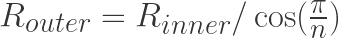
The faceting error comes about from CAD programs using the outer circumcircle as the basis for the radius of the polygon.

For a hole you actually need to use the smaller incircle radius. To convert from the incircle radius for a regular polygon with n sides you simply apply the following:
This formula can actually be quite useful for calculating the number of sides needed given a radius and tolerance. Simply re-arrange in terms of n to give:
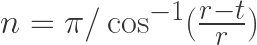
For values of r between 1mm and 20mm, and a tolerance of 0.1mm this gives values for n ranging between 7, and 23. This brings me on to segment pausing. I find it hard to believe that current reprap electronics will have significant delay when trying to produce 23 short line segments. Nophead dismissed this since his electronics were very low latency, and so will I.
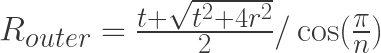
The next factor is arc shrinkage. I found it quite odd that Nophead acknowledged this factor and referenced Adrian Bower’s calculations which compensate for this, but then dismisses it because the numbers come out too small. It occurred to me that Adrian’s calculations are based on a perfect circle, and so the faceting error calculations have to be used in conjunction with arc compensation.
The value for t in this equation needs to be the track width of the extruded path. I wanted to use Slic3r’s formula for this which assumes the area of a track is the same as area of the filament at the nozzle, and that the shape of the track is a rectangle with two semicircles for the sides:

The area at the nozzle is just the area formula for a circle where d is the nozzle diameter:

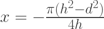
The area of the track is just the sum of a circle area and rectangular area where h is the layer height (which is also the semicircle diameter):

Solving for x when both areas are the same gives:
The total track width then is x plus the width of the two semicircles:
Which gives:
Putting this all together I created this new OpenSCAD script:
| nozzle_dia=0.4; | |
| layer_height=0.3; | |
| function pi() = 3.141592; | |
| function width(d,h) = h-(pi()*((h*h)-(d*d)))/(4*h); | |
| function arc(r,t) = 0.5*(t+sqrt((t*t)+4*(r*r))); | |
| function polyhole(r,n,t) = arc(r,t)/cos(180/n); | |
| function sides(d,t) = ceil(180 / acos((d-t)/d)); | |
| module hole(d,h) | |
| { | |
| n=sides(d,0.1); | |
| t=width(nozzle_dia,layer_height); | |
| pr=polyhole(d/2,n,t); | |
| echo(d,n,pr*2); | |
| translate([0,0,-1])cylinder(r=pr,h=h+2,$fn=n); | |
| } | |
| module main() { | |
| difference() { | |
| linear_extrude(5) { | |
| hull(){ | |
| rotate([0,0,-46.5]) | |
| translate([5,2]) | |
| square([0.001,168]); | |
| rotate([0,0,-43.5]) | |
| translate([-5,2]) | |
| square([0.001,168]); | |
| } | |
| } | |
| rotate([0,0,-45]) | |
| for(i=[1:0.5:10]) | |
| translate([0,i*(i+6),0])hole(i,5); | |
| } | |
| } | |
| translate([10,10,0])main(); |
Here are the results:

Every drill bit fit snugly in the hole it was meant for. Even the small sizes worked surprisingly going down to a 1mm drill bit. But wait… I haven’t accounted for corner cutting. Well this is the aspect where I think I am going to have to disagree with Nophead. Not least because I didn’t account for it in my test above, but also because the assumption is that the filament is being stretched as it goes round corners, and this seems wrong to me. Surely the filament should be being extruded at a rate equal to the motion of the nozzle so that no stretching should occur. In fact in contrary to this Slic3r utilises a faster motion than the extrude rate to deliberately stretch the filament for making bridges, but not during normal perimeter generation. Its odd because Nophead says this is this is the dominant effect on his machines, and is the main justification for using less facets for the holes. Perhaps his extrusion rate is lower and so the filament does get stretched.
For holes below 2mm in diameter Nophead’s formula says you need 4, or 3 facets, which are not really holes at all. I would argue that smaller holes require a higher tolerance to produce accurate results, and from the formula for n above that means you need more facets, not less.
You can really notice the how the difference in facets effects the quality of the holes in the two test pieces:
As a final note I thought its worth mentioning that even a machined hole will be considered an interference fit (tight) if its drilled at the same diameter as the shaft or bolt that its intended for. For this reason a table of clearance holes is used
| Size | Pitch (mm) | Tapping Diameter (mm) | Clearance Holes (mm) | ||||
| Coarse | Fine | Coarse | Fine | Close | Medium | Coarse | |
| M1.6 | 0.35 | 1.25 | 1.7 | 1.8 | 2.0 | ||
| M2 | 0.4 | 1.6 | 2.2 | 2.4 | 2.6 | ||
| M2.5 | 0.45 | 2.05 | 2.7 | 2.9 | 3.1 | ||
| M3 | 0.5 | 2.5 | 3.2 | 3.4 | 3.6 | ||
| M4 | 0.7 | 3.3 | 4.3 | 4.5 | 4.8 | ||
| M5 | 0.8 | 4.2 | 5.3 | 5.5 | 5.8 | ||
| M6 | 1.0 | 5.0 | 6.4 | 6.6 | 7.0 | ||
| M8 | 1.25 | 1.0 | 6.8 | 7.0 | 8.4 | 9.0 | 10.0 |
| M10 | 1.5 | 1.25 | 8.5 | 8.7 | 10.5 | 11.0 | 12.0 |
| M12 | 1.75 | 1.25 | 10.2 | 10.8 | 13 | 14 | 15 |
| M16 | 2.0 | 1.5 | 14.0 | 14.5 | 17.0 | 18.0 | 19.0 |
| M20 | 2.5 | 1.5 | 17.5 | 18.5 | 21.0 | 22.0 | 24.0 |
| M24 | 3.0 | 2.0 | 21.0 | 22.0 | 25.0 | 26.0 | 28.0 |
| M30 | 3.5 | 2.0 | 26.5 | 28.0 | 31.0 | 33.0 | 35.0 |
| M36 | 4.0 | 3.0 | 32.0 | 33.0 | 37.0 | 39.0 | 42.0 |

Hi Giles,
Interesting article.
My polyhole method sidesteps the issue of round holes by making them low count polygons. I use it so that I or anybody else can print my objects on any printer, with any layer height and as long as the printer gets straight lines in the right place they work. They should print the right size no matter what layer height, etc. For example the 2mm holes is a square. If that doesn’t come out the right size then your printer / slicer is not correct. Does a 10mm square hole come out 10mm across?
Compensating for truly round holes is a bigger problem that depends on a lot of variables like layer height / width and viscosity, etc.
When I print your test piece the holes are all too big. Now that is odd since I wrote that Adrian’s compensation was not enough. I think that is because I was considering holes with 32 sides and so the cos(180/n) correction is much smaller, leaving just Adrian’s, which is not enough on its own for 32 sided circles.
I think your maths is slightly wrong though because I think the cos(pi/n) should be applied first to get the bigger circle then expanded by Adrian’s formula. I.e. :-
function polyhole(r,n,t) = arc(r/cos(180/n),t);
That produces a slighly smaller expansion but I haven’t tried it yet. I suspect it will still be too big because it applies to a true circle, not a polygon. So I don’t think it is mathematically valid to reduce the sides to a small number and then apply it. The effect is only at the corners, which are far enough off the circle for it not to matter, or matter less. That is how polyholes work.
When I refer to filament being stretched I mean the cross section is less than the die swell size it would be if extruded into mid air. If you extrude it with the same cross section as the nozzle it will be stretched as it always comes out bigger when not pulled.
The corner cutting I refer to is like the path followed by the rear wheel of a bicycle and gets worse the more you stretch the filament. It’s like having a longer bike.
Looking at your picture it looks like you are using multiple outlines. Depending on the order that may be why your polyholes are too small.
I printed it again with my small change to the formula. My drills fit one slot further down, so the holes are fairly consistently 0.5mm too big.
So it seems your machine prints holes 0.5mm smaller than mine!
Hi Nophead,
Thanks for taking the time to reply and do further tests. I think you’ve cleared up a few misunderstandings I had about your motivation to use low facet count polygons.
Ultimately I am interested in compensating for truly round holes, which is as you say a bigger problem. My reason for applying the faceting error after the arc compensation is because Adrians formula is based on a perfect circle, in this case his value for n would be infinity.
I think if you want to apply the faceting compensation to Adrians formula you would have to calculate the area differently. It would be the sum of n trapezoidal sections. The way I see it, you start with an perfect inner circle of radius R, and expand that with respect to t using Adians formula. However this still gives you the inner circle radius for the hole, and the CAD program (OpenSCAD/RapCAD) expects an outer radius, so you have to expand it further with respect to n.
Regarding the corner cutting, I am sure that the fluid dynamics here are difficult to model. Your rigid body example is a good analogy, but its not exactly whats going on. In the other extreme if, instead of molten plastic being extruded from the nozzle, we were letting water flow out, it would be hard to imagine that there would be any tendency for the flow to be pulled towards the middle of the hole.
Whatever the mystery shrinkage factor is, lets call it m (for mystery). It must be something that is more dominant on my machine and less so on yours. I am going to do some more test prints, and share my Gcode to see if it can be further narrowed down. You are correct that I am using more than one perimeter in my Slic3r settings. I usually use three (which is the default). The perimeters are printed outer one last, which is the smallest perimeter last in the case of holes.
The other thing which I don’t understand is on your original blog post you wrote “These two tests where done on HydraRaptor extruding 0.375mm filament from a 0.4mm nozzle.” Is 0.375mm your layer height, or your track width? Track widths as calculated by the Slic3r formula seem to be greater than the nozzle diameter, not smaller.
You can’t span a bridge if you are printing with a liquid like water, so it is clear we are printing something more solid that can be stretched and has tension. You can observe this when spanning bridges. The lower the cross section of filament used the tighter the span is and the less it droops until you reach the point it snaps.
Holes shrink less with PLA than ABS and a lot more with HDPE, so the viscosity definitely affects it. Also it will cut corners more when extruded from a bigger nozzle, everything else being equal. So you can’t compensate with just maths unless you incorporate viscosity and tension into the model. I also know that printing thinner layers with the same nozzle and the same width will cause them to shrink less.
If you print holes with 3 outlines from the outside in then they will be too small as they don’t pack together without a void because the second and third outlines are bounded on only one side, so spread more the other way, inwards. See http://hydraraptor.blogspot.co.uk/2014/06/why-slicers-get-dimensions-wrong.html. For accurate dimensions you want one outline or at least to print the outer perimeter first. Outer last is better for appearance though.
If you print my polyholes with a single shell I think they work for you and yours will be too big.
If you print thin layers of PLA at high temperature then I think Adrian’s formula will be pretty close, but only if you have enough line segments for it to class as a circle. Sublime always claimed his holes didn’t shrink at all on a Tantalus but he did them at 0.1mm, as wide as his nozzle (0.5mm) and with very liquid PLA.
Yes my post mentioning 0.375mm filament means 0.375 layers and the width would be 1.5 times that, which is wider than the nozzle. When I tested your object I used 0.4mm layers, 0.6mm wide and replaced your width function with h * 1.5 as I am telling Skeinforge the width, not letting Slic3r decide it.
See http://hydraraptor.blogspot.co.uk/2009/01/new-years-resolution.html for a clear demonstration of corner cutting.
I don’t doubt that viscosity is a factor. The point of the example was to show the other extreme. You could argue that even though water has a very low viscosity the effect would still be present. Likewise the steel of a bicycle frame has extremely high viscosity in your example.
I have now printed a test piece with square holes. I took the original script using your original polyholes function, and set . Basically the holes are too small! pointing to the problem with Slic3r as you mentioned in your other post.
I had rather assumed that Slic3r was accurate in this respect since everybody seems to be using it and recommending it. The funny thing is, I know that Slic3r has been updated to use the rounded rectangle formula as mentioned above. The problem must be related to the underlap bulge that you also mention in your post.
I am now going to try all the tests again with single outlines.
Viscosity definitely has an effect because the more viscous it is the more die swell you get. That means to stretch it back down to the required cross section generates more tension. You are right that for tension we also need to know the modulus of the plastic while it is molten as it is elastic.
Then fact a bicycle is rigid is not relevant. It is not the same mechanism as the plastic cutting corners but I think the path is probably the same if you set the length of the bicycle to a suitable value dependent on the plastic.
Somebody added the bicycle compensation to Cura but the last I heard it wasn’t accepted for merging. I have since unsubscribed from Cura, Slic3r, Marlin and Smoothieware as they all infuriate me too much. I only follow OpenScad and OctoPrint these days.
The problem with multiple shells isn’t unique to slic3r. I think all slicers will produce outlines too big and holes too small unless you do the outermost shell first. To get it right you would need to model the voids and that again depends on viscosity. Even for a single plastic I think it would depend on temperature. Or you can model all the shells as rounded beads and have them just touching. The problem then is it will be weak.
I think I have misunderstood the “bicycle effect” then. Perhaps you could point me at some physics literature. What came to mind initially was this minute physics video, which is unfortunately completely irrelevant, but interesting nonetheless. https://www.youtube.com/watch?v=iFwfexZstO4
Here is the pull request where I heard of this technique https://github.com/Ultimaker/CuraEngine/pull/94. It also has a link to the maths and some animations.
If you walk the front wheel around a circle, the back wheel will trace a smaller circle. If the front wheel follows a polygon the back wheel will be a polygon with rounded corners. Note you can’t ride like that! So it isn’t a realistic thing a bike would do, but a mathematical construction.
Regarding triple outlines, I think you would need to use three times the track width in Adrian’s calculation.
I was thinking about this whilst off to sleep last night. My thoughts were, If a bicycle has its steering column set to 90° then the circle that the front wheel takes, has a radius of the bike length, and the smaller circle is 0 (it swivels on the back wheel as a pivot) If the steering column is set to 0° the bike is on an infinite circle, and the front and back wheel radius are the same. If the angle is set to 45° my guess is that the difference between the two circles will be half the length of the bike.
Increasing the length makes the problem worse, but so does increasing the angle. Since lowering the polygon count increases the length of the sides but also increases the angle, does this mean an optimum number of sides can be deduced rather than discovered by observation?
I think the maths involved in calculating and simulating the viscosity would be tough, and the variables needed to get the simulation to match real world examples are not easy to measure. So instead I would rather focus on the issue caused by having multiple outlines. For me having multiple outlines is a bonus, and the order Slic3r does them doesn’t seem to be configurable.
I have removed the test piece from thingiverse because I think its misleading. But I do intend to research the problem further.
The bike doesn’t have a set steering column angle. The front wheel follows the curve and is always aligned tangential to it. The back wheel trails behind and that determines the angle of the steering column at any instance. The back wheel will always move in the direction directly towards the front wheel at any instance.
I don’t know if it is an accurate model of what happens but if it is then rather than trying to model viscosity, etc you just have to empirically find the length of the bike for each filament type and width, etc, by printing various size holes and measuring them.
According to electocbd holes get corrected by D = sqrt(D^2+S^2) but he applies that to general curves as well. I am not sure if that us the same as Enrique does in Skeinforge Stretch. The compensation belongs in the slicer, not the model. I.e. oversize holes in the model suitable for one persons printer are not suitable for another, as we found with your test piece.
Yes multiple shells are good for strength. I tend not to use them though because Skeinforge doesn’t handle the case where there isn’t room for them properly. In some circumstances there is a gap between the outer shell and an inner one because the inner one can’t get into a sharp corner because it isn’t wide enough for two filaments. There should be some infill there but SF only does infill inside the inner shell. On the plus side SF joins the ends of the infill to make a second shell for free, which the other slicers don’t, see http://hydraraptor.blogspot.co.uk/2008/04/python-beans-make-object.html.
We are both right, we are just saying it in different ways. Here is a fun little OpenSCAD animation for you
This file contains hidden or bidirectional Unicode text that may be interpreted or compiled differently than what appears below. To review, open the file in an editor that reveals hidden Unicode characters.
Learn more about bidirectional Unicode characters
bicycle-animation.scad
hosted with ❤ by GitHub
Set to 0 and you will see that the front wheel is at 90° Set
  to 50 (half the length of the bike) and you will see the front wheel at about 45° Like I guessed.
What I got wrong however is that the angle the front wheel makes to the frame is inextricably linked to the radii of the circles. So there is no optimum, you just have to plug in a value for stretch, as you said.
What I find interesting is the geometic similarity of this formula to Adrians formula, perhaps that explains why given empirically selected values of S or t, both have proven successful within their results.
With you saying it is like Adrian’s made me realise Adrian’s formula includes the offset of t/2 which the nozzle needs, but that should not be in your formula as you are calculating the circle diameter, not the tool path. That will be why I dismissed Adrian’s formula as far too small because if you look at his table and subtract 0.25 from all the values the correction is minute, 0.03 for 1mm. That is why your results are basically ~0.5mm too big on my machine. They will be t too big and and that is 0.6mm on my test print.
If you take out t/2 then it is basically the same formula as electrocbd’s with s = t. It is also Pythagoras with the corrected radius being the hypotenuse of a right triangle with d and s. If you scale s then I think it is a right triangle with the radius which can be interpreted as the front wheel on a tangent s/2 long.
I think that means you need quite a long bike to correct the type of contraction I see with ABS, certainly in comparison to the filament width.
Bingo!, I was just thinking the same thing about Adrian’s formula… Is this what you mean.
Solving for s gives:
Yes it seems eloctocbd’s s is Adrian’s t/2 but to have any affect he must use a value much bigger than half the filament width.
Indeed Adrian even mentions this in his wiki page:
The only explanation that makes sense to me is that perhaps he stumbled across the right equation by chance, but because he used an empirical value of much bigger than expected he actually was compensating for corner cutting instead.
Yes but he says he scales it, (presumably just the sqrt term) so k * sqrt(R^2 + S^2) but that is not the same as increasing S beyond t/2 as electrocbd presumably does.
Also there is the issue of the number of sides. When it is small enough no arc compensation is needed because the cut corners are outside of the circle, but you do need the cos()/n compensation for the sides. When the number of sides is large you need the arc compensation but the cos()/n becomes negligible. I wonder what happens when you have an intermediate number of sides? You need arc compensation at the corners but cos()/n compensation for the sides.
Hi Giles,
I removed the extra t/2 term and printed the part again. I measured the holes with digital callipers and plotted the errors on graph. It was extremely random as it is hard to measure slightly polygonal holes in a soft plastic accurately. The average errors was about 0.2mm so I set the formula to this: –
function arc(r,t) = sqrt(t * t / 4 + r * r);
function polyhole(r,n,t) = arc(r/cos(180/n),t) + 0.1;
That gives holes that fit my drills well. Oddly they are a bit loose in the mid range and tighter at each extreme. However drill shanks are a little bit undersized compared to the tip so not the most accurate gauge.
Adding a constant was not at all what I expected as the effect must taper off eventually because I don’t think my straight dimensions are 0.2mm out, although I haven’t checked recently. I don’t think increasing s would work because its effect falls off too quickly to ever affect a 10mm hole without making small holes way too big.
Possibly reducing the number of vertices for small holes clouds the issue because the cos expansion produces such a big effect and it isn’t really a circle any more.
Actually I have just realised my tests are not valid. The change needs to be done in the slicer and can’t be simulated in the model because the stretch algorithm is supposed to change the tool path without changing the amount of plastic. The same with Adrian’s I think.
Hey Nophead,
Thanks for continuing to research this, its a fascinating problem 😉 I’ve started to try and think about these formula in terms of polyhedral circles instead of perfect circles…
If my maths is correct there should be pi * t^2 / n at each corner but there is actually sin(pi/n) * t^2. n * sin(pi/n) tends to pi as n tends to infinity and has a sharp knee around n = 4. Could this be the reason for corner cutting? I always thought there was too much plastic at the corners, not too little. Do you get the same result?
I think if the nozzle takes the corner with a radius of t/2 you get the same shape with the right amount of plastic.
I think I will have to mull this over. How did something so simple suddenly get so much more complicated 😉
Actually I think I may be confused by your drawing. You have the outside corner radius = t but I think it should be t / 2. I.e. don’t we get the chain hull of circles with the diameter t if we ignore viscosity?
There is a paradox though because a chain hull of circles (which is what would get with a pen plotter) doesn’t have a constant width at the corners unless the tool path corners are rounded with an arc of radius t, and then you get what you have drawn.
RapCAD and OpenSCAD don’t have the chain hull module. But OpenJSCAD has it.
Here is a script I created:
function main() {
var c = [];
for (i = 0; i <= 7; i++) {
a=(360*i)/7;
x=40*sin(a);
y=40*cos(a);
c.push(circle(5).translate([x,y,0]));
}
return chain_hull(c);
}
Try it at http://openjscad.org/ (copy paste, then press SHIFT+Return) It looks like my drawing though so its correct yes?
Actually it turns out a chain_hull module is as simple as this in OpenSCAD:
module chain_hull() {
for(i=[0:$children-2])
hull() {
children(i);
children(i+1);
}
}
No it subtly different from you drawing. The corner radius is half as much. You can’t assemble the corner pieces into a circle.
Here is an OpenSCAD script that shows the difference.
$fn = 32;
w = 0.5;
n = 4;
r = 2 / cos(180/n);
difference() {
// Chain hull of circles same width as filament at nozzle positions
for(i = [0 : n – 1])
hull() {
rotate(i * 360 / n + 180 / n)
translate([r + w / (2 * cos(180 / n)), 0])
circle(d = w);
rotate((i + 1) * 360 / n + 180 / n)
translate([r + w / (2 * cos(180 / n)), 0])
circle(d = w);
}
//
// Constant width path that gives the same interior shape
//
rotate(180/ n) difference() {
offset(w) circle(r = r, $fn = n);
circle(r = r, $fn = n);
}
}
I guess its hard to visualise. Based on observation the lower count polygons from the original polyholes seem to look like my drawing. But the ones based on my revisited polyholes look more like a chain hull of circles as you describe.
Great… That makes the maths even more complicated! Furthermore this is just a geometric calculation of area, it has nothing to do with a polyhedral tractrix, or fluid dynamics.
Nophead, I am confused how the filament can get bigger at the corners I modified your script to visualise this:
This file contains hidden or bidirectional Unicode text that may be interpreted or compiled differently than what appears below. To review, open the file in an editor that reveals hidden Unicode characters.
Learn more about bidirectional Unicode characters
confused.scad
hosted with ❤ by GitHub
Because the tool path from the slicer is a square with vertices in the positions I calculated. So if you imagine a pen with a diameter equal to the filament width it would trace the chain hull. It is wider at the corner because you are measuring it diagonally. Just as a picture frame is thicker if you measure it diagonally at the corner. It will be sqrt(2) * w/2 + w/2 for a square with rounded corners.
To get the nozzle in the position you have shown the tool path would need to shortcut the corner with a 90 degree radius equal of w/2. The outside edge then has a radius of w.
When it follows a square cornered tool path it extrudes w^2, enough to make a square corner. However the outer corner can’t have a radius less than the filament width, so there is too much plastic. I think this ends up making a fillet on the inside of the corner.
On the other hand I think it takes the shortcut then it extrudes pi * w^2 / 4 to fill an area pi * w^2 / 4.
It’s getting late, I will check the maths again tomorrow.
Assuming that we can treat arcs as adding up to a small circle then the following mathematics follows.
If arc compensation is only needed in the corners, then you only need to compensate for the small circle on the right. For Adrian’s formula you would set R=0 and this gives which solves to
But if you increase R by that amount then the straight sections will be wrong. So you need to include the straight sections into Adrian’s formula after all.
The area of those sections that contribute to is the length of the side of a polygon times its width given by
  where a is the incircle radius. There are n of those sections giving:
The area of the small circle that contributes to is
is  which gives
Bringing this together gives:
Putting that into the original formula:
Which I think is:
I don’t follow your logic here.
The straight lines are exactly in the right place when adjusted by cos(pi/n).
If you apply Adrian’s formula to the corners you get (t+sqrt(t*t ))/2 = t. I.e. the tool path to draw part of a circle radius t is t instead of t/2. I am not sure the formula is valid for such an extreme case. If it is then you have a mismatch where it meets the straight lines. You would have to blend them into lobes at each corner running at twice the speed because you don’t want any more plastic, just a longer tool path. Not very practical.
Yes I agree. I don’t think that formula works because it makes too many assumptions.
I am trying to visualise the polygon again in terms of the tool path. I took the original heptagon and offset the hole outline by I then drew the following with circles of diameter t.
You can see above that offsetting the circles by t/2 radially is not enough because the filament is wider at the corners. It doesn’t get the edges in the right place. Have a look at my script which offsets it correctly for being along a diagonal. This is what a slicer actually does.
Imagine a square: the slicer will offset the walls by t/2 both horizontally and vertically. Measured along the diagonal “radius” it is t / sqrt(2).
Or perhaps that is what you did if you offset the edges rather than the vertices.
BTW, what do you use to show equations and diagrams like the above in blog comments?
I think I have constructed the polygon correctly. Either that or I am now thoroughly confused.
I use the Latex plugin built in to WordPress to do the equations, (I hope they display properly in your feed reader) https://en.support.wordpress.com/latex/
This is probably more useful for you if you want to quickly add equations to your own blog http://irrep.blogspot.co.uk/2011/07/mathjax-in-blogger-ii.html The diagrams are just screenshots from LibreCAD drawings.