After my discussion with Nophead in my previous post I realised that my attempt to compensate for hole shrinking was flawed. It seems that the dominant effect wasn’t what I thought but turned out instead to be the number and order of perimeters I was using in my Slic3r settings.
This has already been researched before, but I decided to investigate it further. This time I used RapCAD to generate the test pieces since its multi-material support made creating the Slic3r print modifiers a doddle.
| module main(){ | |
| difference(){ | |
| cube([100,17,5],true); | |
| for(i=[-2:2]) | |
| translate([i*20,0,0]) | |
| cube(6,true); | |
| } | |
| } | |
| module mods(){ | |
| for(i=[-2:2]) | |
| material() | |
| translate([i*20,0,0])cube([20,30,10],true); | |
| } | |
| main(); | |
| //mods(); |
I decided to use square holes since I can then measure them accurately with a digital vernier calliper.
Because of the way Slic3r handles multi materials, and modifiers I had to export the main() part first, then comment it out and export the mods() as a separate multi material part.
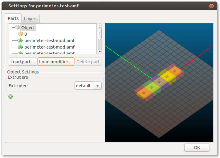
I applied the mods such that the first hole had 1 perimeter, the second 2 perimeters, etc. up to 5 perimeters. Unfortunately Slic3r decided to add extra perimeters internally to the part. This is probably a Slic3r bug but not a problem for this test piece.

I printed the parts out and took 4 measurements of each hole, 2 widthways and 2 lengthways. I then took the average of these four measurements and subtracted them from the specified width of 6mm to get the error. I divided this value by two since this error is doubled up, (there are two sides to the hole).
The blue line in this graph shows the results:
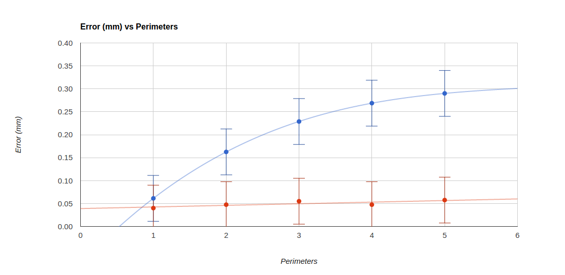
The red line shows the results from a second test piece in which the “Print outer perimeters first” setting was used.
So in summary I don’t think I’ve learned anything new here. Outer perimeters first seems to be the solution as has been suggested before. I was quite surprised to find that the error to perimeters relationship is not linear, but this might be due to errors in measurement, since there is a straight line that goes between all the error bars.

The RSS view of your post has a graph and conclusion but the page view is cut short.
I think it is non-linear because the head is offsetting by the desired width each time but the filament is actually growing faster. So each shell gets printed with the nozzle closer to the previous one. That helps force the plastic in that direction and reduces the void.
In fact I concluded some time ago that the nozzle should only be placed in the centre of the filament path when it is doing the outer shell. For paths where it is bounded on one side only it would be better placed as close as it can be to that side without blocking the orifice. That gives the smallest voids and the strongest object.
What nozzle size and extrusion width are you using? I have a hypothesis that setting the extrusion width to nozzle diameter + layer height or higher (in conjunction with careful e_steps calibration) will mitigate this effect, at least to some degree. This also seems to help with overhangs, which are the big reason for not printing outer perimeters first. I’d be interested to see the results of the same test with a greater extrusion width.
It’s a 0.4mm nozzle with a 0.3mm layer height. The extrusion width is the one auto calculated by Slic3r which is ≈0.48mm
It would be interesting to test with the extrusion width set higher, adding layer height so that you can (in theory) get the entire “racetrack” shape with each pass, rather than just the first one. I suspect that this will actually result in better squeezing of the plastic into the space around left by the previous pass. Also, of course, the increased width/thickness ratio is beneficial, not just for decreasing voids as nophead says, but it’s also good for overhangs and (at least worst-case) inter-layer contact area. Printing this way also seems to yield better optical properties when printing with translucent filaments.
There’s a lot of discussion on the pros/cons of different values for extrusion width here: https://groups.google.com/forum/#!topic/3dp-ideas/2FG_gUxa_fE
Basically the bigger the width to height ratio of the filament the smaller the voids due to the rounded edges are, so the less the error is. Also with less viscous plastic, e.g. PLA printed at higher temperatures, the less the error is.
Would it be stronger to keep the extrusion width the same and shrink the exterior perimeters to compensate for the error.