After my discussion with Nophead in my previous post I realised that my attempt to compensate for hole shrinking was flawed. It seems that the dominant effect wasn’t what I thought but turned out instead to be the number and order of perimeters I was using in my Slic3r settings.
This has already been researched before, but I decided to investigate it further. This time I used RapCAD to generate the test pieces since its multi-material support made creating the Slic3r print modifiers a doddle.
This file contains hidden or bidirectional Unicode text that may be interpreted or compiled differently than what appears below. To review, open the file in an editor that reveals hidden Unicode characters.
Learn more about bidirectional Unicode characters
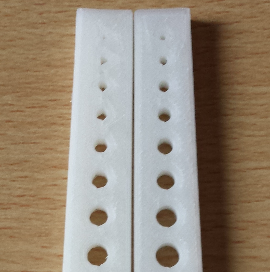
I decided to use square holes since I can then measure them accurately with a digital vernier calliper.
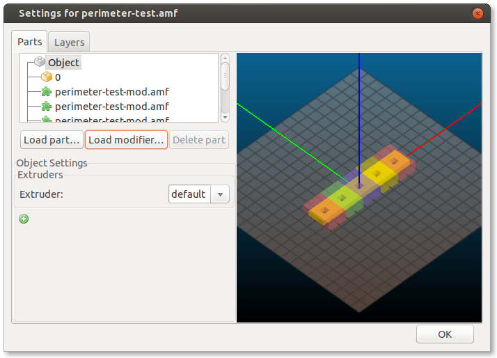
Because of the way Slic3r handles multi materials, and modifiers I had to export the main() part first, then comment it out and export the mods() as a separate multi material part.
I applied the mods such that the first hole had 1 perimeter, the second 2 perimeters, etc. up to 5 perimeters. Unfortunately Slic3r decided to add extra perimeters internally to the part. This is probably a Slic3r bug but not a problem for this test piece.
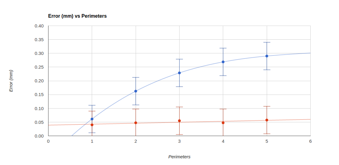
I printed the parts out and took 4 measurements of each hole, 2 widthways and 2 lengthways. I then took the average of these four measurements and subtracted them from the specified width of 6mm to get the error. I divided this value by two since this error is doubled up, (there are two sides to the hole).
The blue line in this graph shows the results:
The red line shows the results from a second test piece in which the “Print outer perimeters first” setting was used.
So in summary I don’t think I’ve learned anything new here. Outer perimeters first seems to be the solution as has been suggested before. I was quite surprised to find that the error to perimeters relationship is not linear, but this might be due to errors in measurement, since there is a straight line that goes between all the error bars.
Some time ago Nophead did some experiments to investigate why holes printed by reprap machines come out undersized.
I’ve also noticed this in my prints and have in some cases manually just ‘added a bit’ and re-printed the part. This isn’t very methodical so I decided to give Nopheads polyholes compensation a try. However even on paper the hole sizes suggested seem to be lower than some of the values I found by trial and error.
I decided to do a formal test and came up with the following OpenSCAD script. I have a full range of 19 drill bits from 1mm up to 10mm in 0.5mm increments.
This file contains hidden or bidirectional Unicode text that may be interpreted or compiled differently than what appears below. To review, open the file in an editor that reveals hidden Unicode characters.
Learn more about bidirectional Unicode characters
The polyholes function is left untouched from Nopheads original and the rest just creates a nice shaped test piece.
Unfortunately the test confirmed what I suspected, and not a single drill bit fit in my test piece. In fact I had to shift all the bits up one space, the 9.5mm bit fitting into the 10mm hole and so on. For the smaller hole sizes even this didn’t work.
I decided to revisit the initial effects that Nophead outlined in his post which were:
Faceting error
Segment pausing
Arc shrinkage
Corner cutting
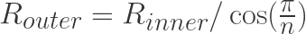
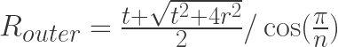
The faceting error comes about from CAD programs using the outer circumcircle as the basis for the radius of the polygon.
For a hole you actually need to use the smaller incircle radius. To convert from the incircle radius for a regular polygon with n sides you simply apply the following:
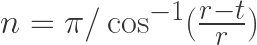
This formula can actually be quite useful for calculating the number of sides needed given a radius and tolerance. Simply re-arrange in terms of n to give:
For values of r between 1mm and 20mm, and a tolerance of 0.1mm this gives values for n ranging between 7, and 23. This brings me on to segment pausing. I find it hard to believe that current reprap electronics will have significant delay when trying to produce 23 short line segments. Nophead dismissed this since his electronics were very low latency, and so will I.
The next factor is arc shrinkage. I found it quite odd that Nophead acknowledged this factor and referenced Adrian Bower’s calculations which compensate for this, but then dismisses it because the numbers come out too small. It occurred to me that Adrian’s calculations are based on a perfect circle, and so the faceting error calculations have to be used in conjunction with arc compensation.
The value for t in this equation needs to be the track width of the extruded path. I wanted to use Slic3r’s formula for this which assumes the area of a track is the same as area of the filament at the nozzle, and that the shape of the track is a rectangle with two semicircles for the sides:
The area at the nozzle is just the area formula for a circle where d is the nozzle diameter:
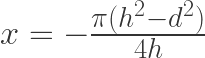
The area of the track is just the sum of a circle area and rectangular area where h is the layer height (which is also the semicircle diameter):
Solving for x when both areas are the same gives:
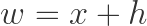
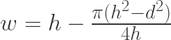
The total track width then is x plus the width of the two semicircles:
Which gives:
Putting this all together I created this new OpenSCAD script:
This file contains hidden or bidirectional Unicode text that may be interpreted or compiled differently than what appears below. To review, open the file in an editor that reveals hidden Unicode characters.
Learn more about bidirectional Unicode characters
Every drill bit fit snugly in the hole it was meant for. Even the small sizes worked surprisingly going down to a 1mm drill bit. But wait… I haven’t accounted for corner cutting. Well this is the aspect where I think I am going to have to disagree with Nophead. Not least because I didn’t account for it in my test above, but also because the assumption is that the filament is being stretched as it goes round corners, and this seems wrong to me. Surely the filament should be being extruded at a rate equal to the motion of the nozzle so that no stretching should occur. In fact in contrary to this Slic3r utilises a faster motion than the extrude rate to deliberately stretch the filament for making bridges, but not during normal perimeter generation. Its odd because Nophead says this is this is the dominant effect on his machines, and is the main justification for using less facets for the holes. Perhaps his extrusion rate is lower and so the filament does get stretched.
For holes below 2mm in diameter Nophead’s formula says you need 4, or 3 facets, which are not really holes at all. I would argue that smaller holes require a higher tolerance to produce accurate results, and from the formula for n above that means you need more facets, not less.
You can really notice the how the difference in facets effects the quality of the holes in the two test pieces:
As a final note I thought its worth mentioning that even a machined hole will be considered an interference fit (tight) if its drilled at the same diameter as the shaft or bolt that its intended for. For this reason a table of clearance holes is used
Its been nearly a year and a half since I last posted about my Reprap Mendel. I haven’t actually made any progress building it either! This is because I got side tracked with other things including developing RapCAD
Well recently I have taken interest again and started meddling with my Mendel. The first outstanding task was to solder the voltage reg and capacitor to the motherboard. I didn’t much like the official reprap solution of powering the motherboard entirely via the usb port! so rather than add a jump wire between the comms port and the 5v track I instead used a spare track to connect a power connector at J4. This still leaves J1 J2 and J3 to be used for additional extruder’s. The motherboard will be powered instead from my previously hacked ATX power supply which will provide 0v 5v and 12v via the XLR connections. For some reason the official reprap uses these 3 wire connectors as well but doesn’t utilise the third wire.
I have been progressing slowly with my reprap build, spending a little time here and there modifying the electronics so that the wiring is neater. There are some details on the reprap wiki about how hack an ATX power supply to give you a universal power supply. This is my sightly neater solution which is specifically suited to reprap only.
With minimal filing the standard ATX power supply grommet hole can be opened out to fit a standard XLR socket. I used a female socket as opposed to the male socket mounted on the reprap. This is standard practice and ensures that the pins of the socket cannot be touched if the connector is removed. In general the live end is protected and the cold end is not.
After a few helpful comments I was pointed in the right direction for drilling a hole down the middle of my hobbed M4 insert. Unfortunately I didn’t have a drill vice, so I used my trusty Block’o’Wood and a fair amount of extra caution instead.
It really is amazing how well this technique works, the drill bit doesn’t have to be perfectly centered but because the work piece is spinning around a central axis its near impossible not to get the hole dead centre. I guess this is why a metal lathe has the drill bit set-up in the tail-stock.
Here is the hobbed insert with the central hole:
I am very pleased with the result, as it runs nice and true when rotated. All I have to do now is drill the M3 grub screw hole.
When I get bored of waiting for someone else to do something I sometimes end up having a go at doing it myself. The hobbed insert in my previous post is no exception
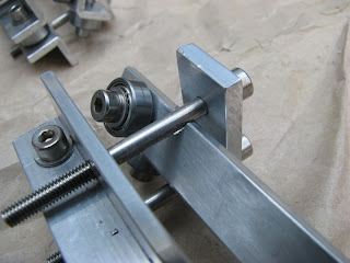
Below is my setup using a drill stand. The 12mm round brass bar is held using a U-Shaped wooden clamp that mounts some 6901ZZ bearings, with an ID of 12mm and an OD of 24mm. I created some dimples on the 12mm brass bar with a punch to create an interference fit in the bearings. This stops things sliding around whilst doing the hobbing. One advantage of the drill stand (which is normally a disadvantage) is that it can swivel around the support pillar. So I was able to push the M3.5 tap closer and closer to the brass bar by pulling the handle to clockwise.
The next problem is how to drill a hole perfectly central down the middle for an m4 tap, again without a lathe. In the meantime the Conrad M4 Inserts have arrived in the worlds most ridiculously over sized box:
I will keep this short and sweet since most of you (in the reprap community) have probably already seen posts like this time and time again. So basically here is a few snapshots of my build progress
Everything went together fairly easily, there were a few minor errors in the assembly instructions which I corrected. The only trouble I had was with Adrian’s geared extruder driver. The base has countersunk holes to fit the heads of M4 bolts, however they were not big enough and reaming them out to 7mm I almost drilled right through. I also felt that the extruder design in general was a bit “bitty” and so I am re-designing the thing from scratch. Here is a sneak peek
The following view shows the lower half of my redesign of the axle mount, it fully encapsulates the bearing rather than having them floating free. (The image shows two separate parts which would be bolted together)
I am intending to also use my internal teeth gear concept with this design
The hobbed insert will soon be available to buy courtesy of raysu in his ebay shop. Price is currently TBC, but he offers similar items at around $8.50
…yes its all the parts needed to build my own Mendel 3D printer! I am really excited about putting them together thanks Joey for such a great gift, how did you know?
Shortly after receiving my gift I dismantled OverlapStrap. I was supprised that the sum of the assembled parts seemed so much more than the 22 bits of MDF 25 bits of aluminium angle and the box full of fixit blocks.
OverlapStrap was by necessity a much simpler design than Mendel. So maybe there is something to be learned from this, although I think designs like the one Josef Prusa has designed and built are even simpler still!
So, the bad news is that I have given up trying to print out all of the Mendel parts using OverlapStrap 😦 However the good news is that I now have a full set of Mendel RP Parts that materialized themselves sometime on Nophead‘s 3D printer(s) and which was then bought from him via his ebay shop. It seems a shame that I didn’t ever fully manage to bootstrap Mendel using my own repstrap, but at the end of the day it was never really my goal. I really started out on this journey because at the time no one seemed to be selling Mendel parts, and of course this is increasingly becoming untrue. I think I have learned a lot putting OverlapStrap together and proved to myself that given enough time, I could have printed out the missing parts and upgraded the machine bit by bit until it had become a Mendel. I believe I have also inspired at least one or two people to create designs that use elements of OverlapStrap, so I think will continue to document and develop OverlapStrap but it is likely only to be driven by other people taking an interest in the design. I never managed to get it running on belts, but I did have designs for how the belt driven “upgrade” would work. For example here are the Y-axis belt idler and motor mounting blocks.
And here is a photo of the x-axis fixit blocks which would have attached to the x-axis motor mounting plate.


