Some time ago Nophead did some experiments to investigate why holes printed by reprap machines come out undersized.
I’ve also noticed this in my prints and have in some cases manually just ‘added a bit’ and re-printed the part. This isn’t very methodical so I decided to give Nopheads polyholes compensation a try. However even on paper the hole sizes suggested seem to be lower than some of the values I found by trial and error.
I decided to do a formal test and came up with the following OpenSCAD script. I have a full range of 19 drill bits from 1mm up to 10mm in 0.5mm increments.
| module polyhole(h, d) { | |
| n = max(round(2 * d),3); | |
| rotate([0,0,180]) | |
| cylinder(h = h, r = (d / 2) / cos (180 / n), $fn = n); | |
| } | |
| module main() { | |
| difference() { | |
| linear_extrude(5) { | |
| hull(){ | |
| rotate([0,0,-46.5]) | |
| translate([5,2]) | |
| square([0.001,168]); | |
| rotate([0,0,-43.5]) | |
| translate([-5,2]) | |
| square([0.001,168]); | |
| } | |
| } | |
| rotate([0,0,-45]) | |
| for(i=[1:0.5:10]) | |
| translate([0,i*(i+6),0])polyhole(5,i); | |
| } | |
| } | |
| translate([10,10,0])main(); |
The polyholes function is left untouched from Nopheads original and the rest just creates a nice shaped test piece.
Unfortunately the test confirmed what I suspected, and not a single drill bit fit in my test piece. In fact I had to shift all the bits up one space, the 9.5mm bit fitting into the 10mm hole and so on. For the smaller hole sizes even this didn’t work.

I decided to revisit the initial effects that Nophead outlined in his post which were:
- Faceting error
- Segment pausing
- Arc shrinkage
- Corner cutting
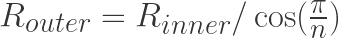
The faceting error comes about from CAD programs using the outer circumcircle as the basis for the radius of the polygon.

For a hole you actually need to use the smaller incircle radius. To convert from the incircle radius for a regular polygon with n sides you simply apply the following:
This formula can actually be quite useful for calculating the number of sides needed given a radius and tolerance. Simply re-arrange in terms of n to give:
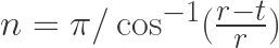
For values of r between 1mm and 20mm, and a tolerance of 0.1mm this gives values for n ranging between 7, and 23. This brings me on to segment pausing. I find it hard to believe that current reprap electronics will have significant delay when trying to produce 23 short line segments. Nophead dismissed this since his electronics were very low latency, and so will I.
The next factor is arc shrinkage. I found it quite odd that Nophead acknowledged this factor and referenced Adrian Bower’s calculations which compensate for this, but then dismisses it because the numbers come out too small. It occurred to me that Adrian’s calculations are based on a perfect circle, and so the faceting error calculations have to be used in conjunction with arc compensation.
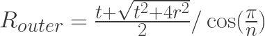
The value for t in this equation needs to be the track width of the extruded path. I wanted to use Slic3r’s formula for this which assumes the area of a track is the same as area of the filament at the nozzle, and that the shape of the track is a rectangle with two semicircles for the sides:

The area at the nozzle is just the area formula for a circle where d is the nozzle diameter:

The area of the track is just the sum of a circle area and rectangular area where h is the layer height (which is also the semicircle diameter):

Solving for x when both areas are the same gives:
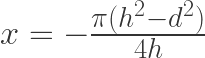
The total track width then is x plus the width of the two semicircles:
Which gives:
Putting this all together I created this new OpenSCAD script:
| nozzle_dia=0.4; | |
| layer_height=0.3; | |
| function pi() = 3.141592; | |
| function width(d,h) = h-(pi()*((h*h)-(d*d)))/(4*h); | |
| function arc(r,t) = 0.5*(t+sqrt((t*t)+4*(r*r))); | |
| function polyhole(r,n,t) = arc(r,t)/cos(180/n); | |
| function sides(d,t) = ceil(180 / acos((d-t)/d)); | |
| module hole(d,h) | |
| { | |
| n=sides(d,0.1); | |
| t=width(nozzle_dia,layer_height); | |
| pr=polyhole(d/2,n,t); | |
| echo(d,n,pr*2); | |
| translate([0,0,-1])cylinder(r=pr,h=h+2,$fn=n); | |
| } | |
| module main() { | |
| difference() { | |
| linear_extrude(5) { | |
| hull(){ | |
| rotate([0,0,-46.5]) | |
| translate([5,2]) | |
| square([0.001,168]); | |
| rotate([0,0,-43.5]) | |
| translate([-5,2]) | |
| square([0.001,168]); | |
| } | |
| } | |
| rotate([0,0,-45]) | |
| for(i=[1:0.5:10]) | |
| translate([0,i*(i+6),0])hole(i,5); | |
| } | |
| } | |
| translate([10,10,0])main(); |
Here are the results:

Every drill bit fit snugly in the hole it was meant for. Even the small sizes worked surprisingly going down to a 1mm drill bit. But wait… I haven’t accounted for corner cutting. Well this is the aspect where I think I am going to have to disagree with Nophead. Not least because I didn’t account for it in my test above, but also because the assumption is that the filament is being stretched as it goes round corners, and this seems wrong to me. Surely the filament should be being extruded at a rate equal to the motion of the nozzle so that no stretching should occur. In fact in contrary to this Slic3r utilises a faster motion than the extrude rate to deliberately stretch the filament for making bridges, but not during normal perimeter generation. Its odd because Nophead says this is this is the dominant effect on his machines, and is the main justification for using less facets for the holes. Perhaps his extrusion rate is lower and so the filament does get stretched.
For holes below 2mm in diameter Nophead’s formula says you need 4, or 3 facets, which are not really holes at all. I would argue that smaller holes require a higher tolerance to produce accurate results, and from the formula for n above that means you need more facets, not less.
You can really notice the how the difference in facets effects the quality of the holes in the two test pieces:
As a final note I thought its worth mentioning that even a machined hole will be considered an interference fit (tight) if its drilled at the same diameter as the shaft or bolt that its intended for. For this reason a table of clearance holes is used
| Size | Pitch (mm) | Tapping Diameter (mm) | Clearance Holes (mm) | ||||
| Coarse | Fine | Coarse | Fine | Close | Medium | Coarse | |
| M1.6 | 0.35 | 1.25 | 1.7 | 1.8 | 2.0 | ||
| M2 | 0.4 | 1.6 | 2.2 | 2.4 | 2.6 | ||
| M2.5 | 0.45 | 2.05 | 2.7 | 2.9 | 3.1 | ||
| M3 | 0.5 | 2.5 | 3.2 | 3.4 | 3.6 | ||
| M4 | 0.7 | 3.3 | 4.3 | 4.5 | 4.8 | ||
| M5 | 0.8 | 4.2 | 5.3 | 5.5 | 5.8 | ||
| M6 | 1.0 | 5.0 | 6.4 | 6.6 | 7.0 | ||
| M8 | 1.25 | 1.0 | 6.8 | 7.0 | 8.4 | 9.0 | 10.0 |
| M10 | 1.5 | 1.25 | 8.5 | 8.7 | 10.5 | 11.0 | 12.0 |
| M12 | 1.75 | 1.25 | 10.2 | 10.8 | 13 | 14 | 15 |
| M16 | 2.0 | 1.5 | 14.0 | 14.5 | 17.0 | 18.0 | 19.0 |
| M20 | 2.5 | 1.5 | 17.5 | 18.5 | 21.0 | 22.0 | 24.0 |
| M24 | 3.0 | 2.0 | 21.0 | 22.0 | 25.0 | 26.0 | 28.0 |
| M30 | 3.5 | 2.0 | 26.5 | 28.0 | 31.0 | 33.0 | 35.0 |
| M36 | 4.0 | 3.0 | 32.0 | 33.0 | 37.0 | 39.0 | 42.0 |
